If your utility is looking at PFAS treatment, there is a very good chance granular activated carbon is on the short list. GAC is the most widely deployed and most studied technology for PFAS removal in drinking water. The EPA designated it as a Best Available Technology in the 2024 PFAS National Primary Drinking Water Regulation[1], and for good reason. It works.
However, "it works" is where the easy part ends. The type of carbon you choose, the contact time you design for, the chemistry of your source water, and how you manage spent media all determine whether your GAC system performs well or becomes an expensive disappointment. I have seen too many conversations stop at "just install GAC" without getting into the details that actually matter. This guide is those details.
I wrote this because I wanted operators and engineers to have one place that covers the practical side of GAC for PFAS, from carbon selection to bed life to reactivation, backed by references you can actually access. If you have already read my PFAS in Drinking Water overview, consider this the deep dive on the treatment technology most of us will encounter first. Let's get into it.
How Does GAC Remove PFAS from Drinking Water?
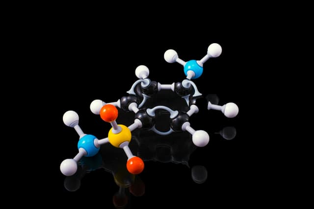
Granular activated carbon removes PFAS through adsorption, a physical process where PFAS compounds bind to the carbon's massive internal surface area. The two primary binding mechanisms are hydrophobic interactions (PFAS molecules are repelled by water and attracted to the carbon surface) and electrostatic interactions between the charged PFAS molecule and the carbon surface[1]. GAC is most effective for long-chain PFAS like PFOA and PFOS but has limited capacity for short-chain compounds, which break through faster due to weaker hydrophobic forces.
Activated carbon is riddled with microscopic pores that give it a surface area of roughly 800 to 1,200 square meters per gram. PFAS molecules flowing through the carbon bed get pulled into those pores and held there. Longer PFAS molecules, with their longer fluorinated tails, have stronger attraction to the carbon and stick more tightly. Shorter molecules have less surface area to grab onto, so they saturate available sites faster and break through into the effluent sooner.
The other critical factor is competition. Your source water is not just PFAS. It contains natural organic matter (NOM), measured as total organic carbon (TOC), and those organic compounds compete with PFAS for the same adsorption sites on the carbon. In waters with elevated TOC, the organic matter can occupy pore space that would otherwise capture PFAS, dramatically shortening the useful life of the carbon[2]. This is the single most important variable operators underestimate when planning a GAC installation. I will come back to it.
GAC adsorption capacity for PFAS is driven by two forces: hydrophobic interactions (stronger for long-chain PFAS) and electrostatic interactions. Natural organic matter in your source water competes for the same adsorption sites, making TOC the single biggest factor in determining how long your carbon will last.
What Type of GAC Is Best for PFAS Removal?
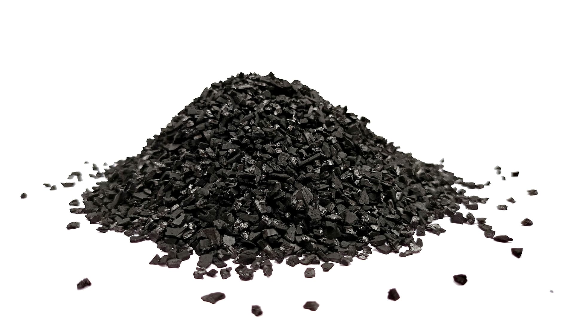
Reagglomerated bituminous coal-based GAC consistently outperforms coconut shell and other non-bituminous carbons for PFAS removal in drinking water. What is reagglomerated carbon? It's a type of high-performance activated carbon (AC) created by pulverizing coal, blending it, and rebinding it to form durable granules. Multiple peer-reviewed studies and full-scale installations confirm that bituminous GAC provides greater adsorption capacity for both long-chain and short-chain PFAS compounds, primarily because its larger transport pore structure allows PFAS molecules to access more internal adsorption sites[3][4].
Not all activated carbon is the same, and for PFAS, the differences are significant. GAC is manufactured from several raw materials, including bituminous coal, coconut shells, lignite coal, wood, and peat[2]. Each source produces carbon with a different pore size distribution, and that pore structure directly affects how well the carbon adsorbs PFAS.
The research on this is fairly clear. McNamara et al. (2018) published one of the first head-to-head comparisons in the Journal of the American Water Works Association, testing reagglomerated bituminous coal-based GAC against coconut shell GAC using rapid small-scale column tests. The bituminous carbon provided considerably greater PFAS removal capacity[3]. Pannu et al. (2023) expanded on this work, evaluating eight different GACs across multiple groundwaters, and found that bituminous products generally showed later initial breakthrough and better long-term performance than non-bituminous alternatives[4].
Why Does Pore Structure Matter?
The explanation comes down to pore geometry. Coconut shell carbons are predominantly microporous, with very small, tightly packed pores. That microporosity is excellent for small molecules like taste and odor compounds, but PFAS molecules (especially long-chain compounds like PFOA and PFOS) are physically larger. They need access to wider transport pores to reach the interior adsorption sites where they bind. Bituminous coal-based carbons have a more balanced pore structure with larger transport pores that allow PFAS compounds to penetrate deeper into the carbon particle[4].
That said, the picture is not entirely one-sided. Some newer engineered coconut shell products are being specifically optimized for PFAS, and coconut shell GAC has real advantages in hardness, sustainability (it is a renewable resource), and performance for certain short-chain compounds. However, for a system being designed from scratch to meet the EPA's 4 ppt MCL for PFOA and PFOS, the weight of evidence currently favors bituminous coal-based GAC, particularly reagglomerated products like Calgon F400 or equivalents.
The Vermont Department of Environmental Conservation's PFAS Treatment Engineering Document (2024) specifically notes that bituminous GACs exhibit higher PFAS adsorption and removal than non-bituminous and sub-bituminous alternatives, and recommends that media selection be guided by site-specific pilot testing[5].
How Do Different GAC Types Compare for PFAS?
| Property | Bituminous Coal | Coconut Shell | Lignite Coal | Wood-Based |
|---|---|---|---|---|
| PFAS Removal Capacity | Highest | Moderate | Lower | Lower |
| Long-Chain PFAS | Excellent | Good | Moderate | Moderate |
| Short-Chain PFAS | Good | Limited | Limited | Limited |
| Pore Structure | Balanced (micro + meso + transport) | Primarily microporous | Primarily macroporous | Macroporous |
| Hardness | Good | Highest | Lowest | Low |
| Sustainability | Non-renewable | Renewable | Non-renewable | Renewable |
| Typical Use for PFAS | Primary choice | T&O, some PFAS | Color removal | Color removal |
The bottom line is to test with your actual source water and the specific carbon products you are considering. The research provides good general guidance, but every source water is different, and the competitive effects of your specific water matrix will influence performance more than any lab study can predict[4].
How Much Empty Bed Contact Time Does GAC Need for PFAS?
Full-scale GAC systems designed specifically for PFAS removal use empty bed contact times (EBCTs) between 7.6 and 26 minutes, with vendors commonly recommending a minimum EBCT of 20 minutes for optimal performance[2]. Higher EBCT means longer contact between water and carbon, better removal efficiency, and longer bed life, but it also means larger vessels and higher capital costs.
EBCT is the single most important design parameter for a GAC system. It measures how long water stays in contact with the carbon bed, and it directly controls how effectively PFAS compounds adsorb. If your EBCT is too short, PFAS molecules do not have enough time to diffuse into the carbon's internal pore structure, and you get premature breakthrough. If your EBCT is too long, you are spending more on vessel size than you need to.
The formula is straightforward:
EBCT (minutes) = Bed Volume (ft³) / Flow Rate (ft³/min)
If your flow rate is in gallons per minute, divide by 7.48 to convert to cubic feet per minute.
Research consistently shows that increasing EBCT improves PFAS removal, particularly for short-chain compounds that are harder to capture. A full-scale study in Sweden found that decreasing flow rate (increasing EBCT) improved total PFAS removal, with the greatest improvements observed for the shorter-chain compounds like PFHxA[6]. This makes intuitive sense. Shorter-chain PFAS have weaker adsorption affinity, so they need more contact time to bind effectively.
For most drinking water applications targeting the EPA's 4 ppt MCL for PFOA and PFOS, an EBCT of 10 to 20 minutes per contactor is a reasonable starting range. Systems using a lead-lag configuration (two contactors in series) will have a combined EBCT that is the sum of both beds, which is one of the reasons lead-lag design is standard practice for PFAS.
What Determines GAC Bed Life for PFAS Treatment?
GAC bed life for PFAS treatment depends on four primary factors: the PFAS compounds present and their concentrations, the background water quality (especially TOC), the type of GAC used, and the EBCT. Bed life is measured in bed volumes (BVs), the total volume of water treated divided by the volume of the carbon bed. For PFAS treatment in drinking water, reported bed lives range from roughly 10,000 to over 100,000 bed volumes depending on these variables[2].
Bed life is what determines your operating cost, because it controls how often you replace or reactivate your carbon. Understanding breakthrough curves and the factors that shorten bed life is essential for anyone planning or operating a GAC system for PFAS.
What Does a PFAS Breakthrough Curve Look Like?
A breakthrough curve plots PFAS concentration in the effluent against the number of bed volumes treated. At the start of a fresh carbon bed's life, effluent PFAS is at or near zero. As the carbon's adsorption sites fill up, PFAS starts appearing in the effluent, initially at low concentrations and then increasing until the effluent approaches the influent concentration. The point at which effluent concentration exceeds your treatment target is when the bed needs to be changed out.
The reason this matters for operators is that PFAS compounds do not all break through at the same time. The elution order is predictable. Short-chain carboxylic acids (like PFBA and PFHxA) break through first, followed by short-chain sulfonates (like PFBS), then long-chain carboxylates (PFOA), and finally long-chain sulfonates (PFOS) last[4][7]. Sulfonates of a given chain length consistently adsorb more strongly than carboxylates of the same length.
If your source water contains a mix of long-chain and short-chain PFAS, you may see short-chain breakthrough months before PFOA or PFOS shows up in the effluent. Whether that matters depends on which compounds you are regulated for. If the Hazard Index for PFHxS, PFNA, GenX, and PFBS survives the D.C. Circuit challenge, short-chain breakthrough becomes a compliance issue, and GAC alone may not be enough.
How Does Source Water Quality Affect Bed Life?
Total organic carbon is the biggest bed life killer. NOM competes directly with PFAS for adsorption sites, and because NOM is present at concentrations roughly 1,000 times higher than PFAS, it can dominate the competition[1]. A pilot study in Eau Claire, Wisconsin demonstrated this dramatically: GAC columns treating water with high TOC showed PFAS breakthrough at approximately 12,000 bed volumes, far earlier than projected, because the organic matter saturated the carbon before PFAS could be fully captured[8].
Pilot test with your actual source water. Bench-scale tests with clean water will overestimate bed life. Rapid small-scale column tests (RSSCTs) using your source water are the standard approach for estimating bed life before committing to full-scale design[2][4].
Other source water factors that affect bed life include competing anions (sulfate, nitrate, chloride), pH, temperature, and the presence of other organic contaminants. Surface water sources generally pose more challenges than groundwater because of higher NOM loading and seasonal variability.
What Is a Lead-Lag Configuration for PFAS Treatment?
A lead-lag configuration uses two GAC contactors in series, where water flows through the lead (first) contactor and then through the lag (second) contactor. When the lead bed reaches PFAS breakthrough, it is taken offline for carbon replacement, the lag bed moves to the lead position, and a fresh carbon bed is placed in the lag position. This design maximizes carbon utilization and provides continuous effluent protection[2].
Lead-lag is the standard design approach for PFAS treatment with GAC, and for good reason. In a single-contactor system, you have to replace the carbon as soon as breakthrough begins, which means you are throwing away carbon that still has unused adsorption capacity in the lower portion of the bed. In a lead-lag system, the lag bed acts as a safety net, catching any PFAS that breaks through the lead bed. This allows you to run the lead bed closer to full exhaustion before replacing it, which means you get more treated water out of every pound of carbon.
The combined EBCT across both contactors is additive. If each bed provides 10 minutes of EBCT, the total system EBCT is 20 minutes. This is another advantage of the lead-lag approach: it provides a longer effective contact time without requiring oversized individual vessels.
If you are familiar with BAC (biologically activated carbon) systems from other treatment applications, the physical setup of a GAC-for-PFAS system will look familiar. The key difference is that for PFAS, you are relying entirely on the carbon's adsorption capacity rather than biological activity. There is no biofilm doing the work here. It is a purely physical adsorption process, and that means bed life is finite and media management is the primary ongoing cost.
Does GAC for PFAS Also Reduce Disinfection Byproducts?
Yes. A study of 19 community water systems that installed GAC, IX, or RO treatment for PFAS found average reductions of 42% for total trihalomethanes (THMs) and 50% for haloacetic acids (HAAs) following installation[9]. These disinfection byproduct reductions represent significant additional compliance value beyond PFAS removal and can fundamentally change the cost-benefit analysis for treatment upgrades.
This is one of the most important and most overlooked aspects of GAC for PFAS. When you install GAC to meet PFAS MCLs, you are simultaneously removing natural organic matter that serves as precursor material for disinfection byproducts. THMs and HAAs form when chlorine reacts with organic matter in the water. Remove the organic matter upstream with GAC, and you reduce the formation of regulated DBPs downstream.
For utilities that are already struggling with DBP compliance under the Stage 2 Disinfectants and Disinfection Byproducts Rule, this is a game changer. The GAC system you need for PFAS compliance may also solve, or at least significantly improve, your DBP situation. That is not a side benefit. It is additional regulatory compliance value that strengthens your business case and your budget justification.
When building the case for GAC installation at your utility, quantify the expected DBP reduction alongside the PFAS removal. Run the numbers on both. A capital project that addresses two regulatory challenges simultaneously is a much easier sell than one that addresses only one.
Can Spent GAC Be Reactivated, and Does That Destroy PFAS?
Yes. Thermal reactivation of spent GAC at full-scale facilities has demonstrated greater than 99.99% destruction of PFAS compounds while restoring the carbon to near-virgin adsorption capacity[10][11]. The reactivation process heats spent carbon to temperatures that break the carbon-fluorine bond, converting PFAS into fluoride salts and carbon dioxide. This makes GAC with thermal reactivation not just a separation technology but a destructive technology when you consider the full lifecycle.
This is worth pausing on, because the question of "where does the PFAS go?" is one that every operator and utility manager should be asking about any treatment technology. With GAC, the answer is clear. You adsorb PFAS onto the carbon during treatment, and then the reactivation process permanently destroys it.
The process works in two stages. First, the spent carbon is heated in a furnace (typically a multihearth Herreschoff furnace or rotary kiln) where PFAS compounds are volatilized from the carbon surface. Then, the volatilized PFAS passes through a downstream abatement system, including a thermal oxidizer, that completes the destruction[10]. DiStefano et al. (2022) published the first peer-reviewed study of this process at full scale and found complete removal of PFAS from the GAC and greater than 99.99% destruction through the combined furnace and abatement system. A follow-up study by Mayerberger et al. (2025) at a potable-classed reactivation facility confirmed these results using updated EPA test methods[11].
Reactivated carbon can be returned to service, reducing the need for virgin carbon and lowering long-term operating costs. There is some carbon mass loss during reactivation (typically 5-10%), so the reactivated product is supplemented with makeup virgin carbon. However, the overall economics are favorable compared to single-use disposal.
The EPA's Technologies and Costs document notes that the most likely management option for spent GAC containing adsorbed PFAS is reactivation, and that several vendor-operated reactivation facilities hold RCRA permits for this purpose[2].
What Should Operators Consider Before Installing GAC for PFAS?
Water treatment professionals planning a GAC installation for PFAS should take seven steps before committing to a design: characterize the source water, pilot test with actual water, select carbon based on PFAS-specific performance data, design for adequate EBCT, plan for waste management from day one, quantify co-benefits for budget justification, and secure available funding through the Bipartisan Infrastructure Law and state programs.
I will be direct. The regulatory uncertainty around PFAS is frustrating, but it is not a reason to delay planning. PFOA and PFOS at 4 ppt are not going anywhere. California has already issued monitoring orders[12]. Many other states have their own notification or response levels. If you do not know what is in your source water, you are behind.
Know Your Source Water First
Source water characterization is step one. Collect samples and test for the full suite of EPA Method 533 or 537.1 analytes, not just PFOA and PFOS. You need to know which PFAS compounds are present, at what concentrations, and whether you are dealing with long-chain, short-chain, or a mixture. You also need to know your TOC, because that will drive your bed life estimates more than almost any other factor.
If your source water comes back clean, your compliance path may be monitoring and reporting rather than a capital project. If PFAS is present, the specific compound profile will determine whether GAC alone is sufficient or whether you need a hybrid treatment train with ion exchange.
Pilot Test Before You Commit
Do not design a full-scale GAC system based on vendor literature or clean-water bench tests alone. Run RSSCTs or pilot columns with your actual source water and the specific carbon products you are considering. The competitive effects of your water's NOM, competing anions, and other chemistry will significantly influence performance and bed life[4][5]. A few months of pilot testing can save years of operational headaches and millions in unexpected carbon replacement costs.
Plan for Waste Management
Every pound of spent carbon contains adsorbed PFAS. You need a plan for that spent carbon before your system goes online. Thermal reactivation is the most established option and has the added benefit of destroying PFAS[10][11]. However, reactivation requires shipping spent carbon to a permitted facility, and those logistics need to be arranged in advance. EPA has not finalized comprehensive requirements for managing PFAS-laden treatment residuals, and that regulatory gap will eventually close. Plan for it now.
Build the Business Case
When you present the capital project to your board or council, do not frame it as just a PFAS expense. Quantify the expected DBP co-benefits[9]. Factor in the compliance value of THM and HAA reductions. Include the potential for cost recovery under CERCLA, since EPA has designated PFOA and PFOS as hazardous substances. And look into available funding: the Bipartisan Infrastructure Law allocated $9 billion for emerging contaminants through the Drinking Water State Revolving Fund, and California and other states have additional grant and loan programs.
Where Does GAC Fit in the Bigger PFAS Treatment Picture?
GAC is not the only tool in the box, but it is the foundation. For systems with predominantly long-chain PFAS (PFOA and PFOS), GAC alone may be sufficient to meet the 4 ppt MCLs. For systems facing a mixed PFAS profile with significant short-chain contamination, the trend across the industry is toward hybrid treatment trains that pair GAC with ion exchange. GAC handles the long-chain compounds and provides DBP co-benefits, while IX catches the short-chain PFAS that break through GAC more quickly.
If you want the full picture of how GAC compares to IX, RO/NF, and hybrid approaches, I covered that in detail in my PFAS in Drinking Water overview. For a deeper look at ion exchange specifically, that guide is coming soon as part of this series.
The DBP co-benefits discussed above also matter on the T-5 exam. If you are preparing for certification, my Stage 1 DBPR and Stage 2 DBPR study guides cover the TTHM, HAA5, and LRAA compliance math that makes TOC removal through GAC so valuable. If you operate in California, the Title 22 Chapter 15.5 guide pairs well with them.
The treatment technology picture for PFAS is maturing fast. GAC has been used for PFAS removal for over 15 years, and the operational track record is extensive. We know how it performs, we know its limitations, and we know how to manage the waste stream through reactivation. For most utilities, GAC will be the first technology deployed, and for many, it will be the primary one.
I will continue covering PFAS treatment developments on H2oCareerPro.com as the technology and regulations evolve. If this guide was useful, I would appreciate you sharing it with a colleague. We are all in this together.
This article is for educational and informational purposes. Regulatory requirements vary by jurisdiction and are actively changing. Consult official EPA, state, and local regulatory sources for current compliance obligations. Nothing here constitutes legal, engineering, or regulatory advice.
Frequently Asked Questions
How long does GAC last for PFAS removal?
GAC bed life for PFAS treatment ranges from roughly 10,000 to over 100,000 bed volumes, depending on the PFAS compounds present, source water TOC, carbon type, and empty bed contact time. For a typical municipal system treating groundwater with moderate TOC, bed life of 20,000-50,000 bed volumes is a reasonable planning range. Pilot testing with your actual source water is the only reliable way to estimate bed life for your specific application.
Is coconut shell GAC good for PFAS removal?
Coconut shell GAC provides moderate PFAS removal but is generally outperformed by bituminous coal-based GAC, particularly reagglomerated products. Coconut shell carbon's predominantly microporous structure limits access for larger PFAS molecules. However, some newer engineered coconut shell products are being optimized for PFAS, and coconut shell has advantages in hardness and sustainability. For systems targeting the EPA's 4 ppt MCL for PFOA and PFOS, the weight of evidence currently favors bituminous coal-based GAC.
Can GAC remove short-chain PFAS?
GAC has limited capacity for short-chain PFAS compounds like PFBA, PFHxA, and PFBS. These compounds break through GAC beds significantly faster than long-chain PFAS due to weaker hydrophobic interactions with the carbon surface. For systems facing short-chain PFAS contamination, ion exchange resin is generally more effective, and many utilities are deploying hybrid GAC + IX treatment trains for comprehensive coverage.
What does GAC thermal reactivation cost?
Thermal reactivation costs vary by vendor and volume but are generally significantly less expensive than purchasing virgin GAC. The process destroys adsorbed PFAS with greater than 99.99% efficiency while restoring the carbon to near-virgin adsorption capacity. There is typically 5-10% carbon mass loss during reactivation, requiring makeup virgin carbon. Contact reactivation vendors for current pricing based on your projected volume and shipping distance.
How does GAC compare to ion exchange for PFAS?
GAC excels at removing long-chain PFAS (PFOA, PFOS) and provides valuable DBP co-benefits by removing natural organic matter. Ion exchange (IX) outperforms GAC on short-chain compounds, achieving 94-99% removal across all six EPA-regulated PFAS with roughly one-quarter the footprint. GAC has lower capital costs but higher ongoing media replacement costs. Many utilities are deploying hybrid GAC + IX treatment trains to leverage the strengths of both technologies.
Studying for the T-5 Exam?
GAC is a core treatment technology for disinfection byproduct compliance. If you are preparing for the California T-5 water treatment operator exam, these free study guides cover the regulations most relevant to GAC design and operation.
- Stage 1 DBPR Study Guide — TTHM and HAA5 MCLs, enhanced coagulation requirements, and how GAC fits into DBP compliance strategy.
- Stage 2 DBPR Study Guide — LRAA compliance, distribution system DBP variability, and the role of GAC in precursor removal.
- SDWA Fundamentals Study Guide — The regulatory framework (MCLs, MCLGs, BATs) that drives every PFAS treatment decision.
References
- U.S. EPA (2024). "Best Available Technologies and Small System Compliance Technologies for the PFAS National Primary Drinking Water Regulation." EPA Document No. 815-R-24-011. EPA BAT Document
- U.S. EPA (2024). "Technologies and Costs for Removing Per- and Polyfluoroalkyl Substances (PFAS) from Drinking Water." EPA Document No. 815-R-24-012. EPA Tech & Costs Document
- McNamara, J.D., Franco, R., Mimna, R., & Zappa, L. (2018). "Comparison of Activated Carbons for Removal of Perfluorinated Compounds from Drinking Water." Journal AWWA, 110(1), E2-E14.
- Pannu, M.W., Orta, J.D., O'Rear, D.J., & Kreuziger, V.J. (2023). "Comparing PFAS removal across multiple groundwaters for eight GACs and alternative adsorbent." AWWA Water Science, 5(4), e1345. AWWA Water Science
- Vermont Department of Environmental Conservation (2024). "PFAS Treatment Engineering Document." VT DEC Document
- McCleaf, P. et al. (2020). "Removal of per- and polyfluoroalkyl substances (PFASs) in a full-scale drinking water treatment plant: Long-term performance of granular activated carbon (GAC) and influence of flow-rate." Water Research, 182, 115968.
- Hopkins, Z.R. et al. (2024). "Predicting per- and polyfluoroalkyl substances removal in pilot-scale granular activated carbon adsorbers from rapid small-scale column tests." AWWA Water Science, 6(2), e1369. AWWA Water Science
- GF Thompson Inc. (2025). "Navigating PFAS: Treatment Strategies for Achieving 2029 Compliance." GF Thompson
- Evans, S. et al. (2025). "PFAS Treatment as an Opportunity for Broader Drinking Water Improvements: Evidence from U.S. Water Systems." ACS ES&T Water. ACS Publication
- DiStefano, R. et al. (2022). "Thermal destruction of PFAS during full-scale reactivation of PFAS-laden granular activated carbon." Remediation, 32, 231-238. Wiley Online Library
- Mayerberger, E.A. et al. (2025). "Destruction of PFAS During Thermal Reactivation of Granular Activated Carbon Used in Potable Water Treatment." Remediation. Wiley Online Library
- California State Water Resources Control Board (2025). "PFAS General Order DW-2025-0002-DDW: Initial Monitoring for PFAS." December 12, 2025. CA SWRCB